Mar 12, 2019 - Nixie MultiMeter, Part 18
More Power Analysis
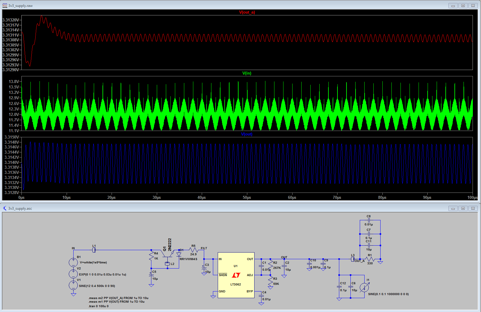
I was curious and I already had a pretty decent simulation of my linear regulator in LTSpice, so I spent some more time playing with it to see how the filtering between the digital and analog sides would work.
What I found surprised me a bit: under a 100kHz, 0-200mA sinusoidal load, the output voltage has 40mV of ripple. (Increasing the frequency reduces the ripple). I’m not surprised that there’s ripple under load, but the magnitude of it surprised me a bit.
I also modeled TI’s recommended filter and its output into a 10mA resistive load. It definitely helps reduce the ripple, but it also drops almost 0.2V, so I suspect a decent part of the ripple reduction comes from DC resistance of the ferrite bead (15 ohms) forming a low-pass filter with the 22uF capacitor. If I choose a ferrite bead with lower DC resistance, the voltage drop disappears but the ripple gets larger.
Trying to put a filter on the primary load doesn’t seem to help either. The filter’s resistance increases the voltage swing at the primary load, but doesn’t seem to reduce the voltage ripple at the regulator or on the analog side.
Adding 70uF of ceramic capacitors improves ripple significantly, but it’s still around 0.8mV (800uV), and that’s a lot of capacitance!
Replacing the electrolytic capacitor in the analog filter side with a ceramic capacitor further reduces the ripple on that side, to about 10uV.
With a 10uF ceramic capacitor on the analog filter side, removing the 70uF of capacitance on the load side results in about 20uV of ripple on the analog side. Good enough!