Aug 26, 2018 - Nixie MultiMeter, Part 16
Design Completion Checklist
I’m coming up on the end of this project; partly because I’m close to having the schematic complete, and partly because I’m ready to be done. I’ve put together a checklist of the things that I need and want to get done before I start doing PCB layout.
- Must Have
- Higher-power op-amps for resistance drive and virtual ground
- Prevent floating leads/inputs in 4-wire mode
- LEDs for decimal point, range and mode indication
- 3.3V regulator
- Power input jack
- Power supply decoupling for MSP430
- Power supply decoupling for op-amps
- MSP430 programming and debug connector (and cable?)
- MSP430 crystal
- Inter-board connector or cable
- Mode select method (switches, buttons, rotary switch?)
- Optional
- Resistance Calibration Mode(s)
- Try to reduce number of relays to reduce cost
- Look for other easy ways to reduce cost.
- Computer uplink for automated measurement (Serial, USB, or other)
- 3D models for the remaining components that do not currently have models. Not a big deal for small components, but will help verify footprints on more complex items and help visualize the soldering and assembly process.
1.1 Higher Power op-amps
The Art of Electronics (and at least one post on Elecronics StackOverflow) suggest that the easiest ways to get more output current from an op-amp are to either add a pair of BJT transistors in a push-pull output stage, or add a second op-amp to act as a buffer on the output. The only caveat with this kind of design is that the output stage needs to have a higher gain-bandwidth product, to avoid causing delays and phase shifts in the feedback loop.
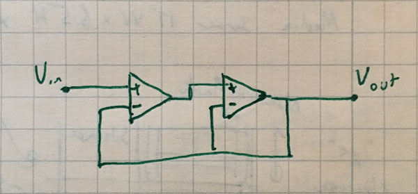
The first op-amp in the chain provides most of the precision, and the second op-amp (or transistors) provides the desired output current.
For the overall circuit, I have the following requirements from previous posts:
- Input Offset 10uV or less
- Input leakage 1pA or less
- Output Current 100mA or more
- Single-ended supply voltage of 3.3V
- Output voltage swing from 0.65V to 2.65V
- No serious bandwidth requirement; circuit is designed for steady-state operation
The input op-amp satisfies the input offset and input leakage requirements, but since it’s only driving the second op-amp, it doesn’t need to satisfy the output current requirement.
The output op-amp satisfies the output current requirement, but since it’s driven from the relatively low-impedance output from the first op-amp, doesn’t need to meet the input leakage requirement. Since the feedback loop is wrapped around both op-amps, the first op-amp can also compensate for substantial input offsets in the second op-amp. The output op-amp should have a higher slew rate and gain-bandwidth product (GBW) to avoid oscillations.
Since both stages have unity gain, the both need to meed the supply voltage and output voltage swing requirements.
The existing LT6078 that I’ve chosen for other parts of the circuit is still one of the best choices for meeting the requirements for the first stage op-amp.
With the reduced requirements on the output stage, there are lots of op-amps which fit the current and supply voltage requirements. The ON Semi LMV358 looks like a reasonable choice, with an output current of 185mA, GBW of 1MHz, rail-to-rail outputs and a supply voltage range of 2.7V to 5.5V. (There were too many choices here, so I rolled the dice and picked one).
That wraps up the selection of the high-power op-amp. Future posts will focus on the remaining items to complete the design.
Home