Jan 31, 2018 - Nixie MultiMeter, Part 10
When I started this multimeter design series, I thought it would be fairly simple and it wouldn’t take very long. It turns out that it’s more complicated than I was expecting, and I’m not one to do things halfway, so here we are at part 10. The finish line is in sight, but it’s probably another few weeks and 10-20 posts.
News and Updates
- Mark Smith (@surfncircuits on Twitter) recently released a design tutorial, parts list and schematics for an Optimized 5V to 170V Nixie Tube Power Supply. I really enjoyed reading though his post and I’m planning to re-use his design as part of my multimeter.
- I found an interesting post by Fluke about selecting the correct fuse for your tester, and it gives a very good overview of why the design of the protection circuitry is so important.
Current Sense Protection, Redeaux
I spend some time over the last few days drawing up and analyzing a potential current measurement circuit with the input protection that I disucssed in the previous post.

For reference and searchability, the table at the bottom is a rough analysis of the circuit performace at maximum rated current and the maximum protection voltage for each range.
| Range | Total Resistance | Voltage Drop @ Range Current | Current @ 200V | Sense Resistor Power @ 200V |
|---|---|---|---|---|
| 10A | 1.5m Ohm | 15mV @ 10A | 1.3 x 10^5 A | |
| 100mA | 150m Ohm | 15mV @ 100mA | 1.3 x 10^3 A | |
| 1mA | 70 Ohm | 70mV @ 1mA | 2.85 A | 122W |
| 10uA | 1.555k Ohm | 15.55 mV @ 10uA | 129 mA | 25W |
There’s a few things to note from this circuit and my rough calculations
- I haven’t accounted for the fuse resistance in the high-current ranges. Given the low sense resistance, it might be important.
- One current sense input is used for all ranges. Having separate inputs for the different ranges is something that has bothered me about most traditional meters, so I designed this to use a single input.
- All of the sense resistors will experience significantly higher power during a short-circuit event. I should check their ratings to make sure that they will withstand that voltage.
- In the 10uA range, there’s not a lot of excess current to activate the PTC. I probably need a bypass diode and resitor on this sense resistor to prevent it from overheating at lower voltages.
- For all of these ranges, an overvoltage input will result in a large voltage at the ADC inputs. I should add a resistor and voltage clamp circuit similar to the one present in the voltage protection circuit.
I’ve had a hard time finding voltage vs current curves for the PTCs that I’d identified in the previous post, so I found another PTC that has better specifications, the EPCOS B59751C0120A070.
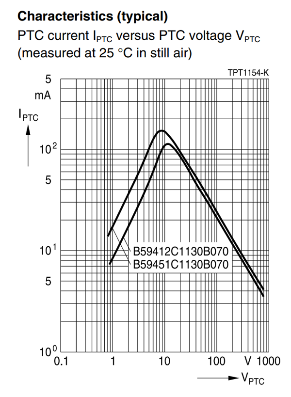
At about 200V, the current through this PTC is about 12mA (plus or minus about 1mA). At nominal voltage, this PTC has a resistance of about 50 Ohms.
| Resistor | Overload Rating | Voltage @ 12mA | Overload Current | Trip Time |
|---|---|---|---|---|
| 15 Ohm | 300V / 5 seconds | 180 mV | 3.07 A | 0.7 sec |
| 1.5k Ohm | 200V / ? seconds | 18 V | 129 mA | No trip |
With the 1.5k Ohm resistor, the overload current isn’t high enough to trip this PTC. Based on the datasheet, the required current to trip in under 1 second is about 2A. To generate 2A, the resistance needs to be reduced to about 100 Ohm total, which would require adding a 50 Ohm resistor, and a bypass diode in parallel with the sense resistor.
If I put the addtional resistor in parallel with the sense resistor, it won’t add any voltage drop, but at overload the sense resistor will still see at least 100V. If I put the additional resistor in series with the sense resistor, it will add a small voltage drop, but at overload the sense resistor will only be subjected to the voltage drop of the diode.
For the high-current resistors, the overload ratings are:
| Resistor | Overload Rating |
|---|---|
| 1.5m Ohm | 15W / 5 seconds |
| 150m Ohm | 200V / 5 seconds |
I’m not completely sure I believe the overload rating on the 150m Ohm resistor, but either way the overload rating on the 1.5m Ohm resistor definitely indicates that I will probably need more than just a fuse to prevent that resistor from overloading.
I suspect the best way to solve this is with a small inductor on the common side of the circuit. I’ve found a few 10A ceramic fuses, and it looks like both of them will open in 1mS or less when subjected to at least 200A, which implies that the inductor needs to limit the rate of change of current to 2 x 10^5 A / s or less. Since V = L * dI/dT, this implies an inductance of about 1 mH will produce the desired current limiting before the fuse blows.
I’m having a hard time coming up with a good way to model this from first principles, so I’m going to model the circuit in LTSpice and see how it responds to a 200V step on the input.
I needed component values for my measurements, so I’ve selected the following components for my model:
- Littelfuse 0157010.DR 10A, 125V AC/DC fuse. 5.8m Ohm nominal resistance.
- Pomona Electronics test leads (Pomona makes very nice leads). 48” each, 18 AWG.
- According to ampbooks.com wire calculator each of these leads should have a resistance of about 2m Ohms and an inductance of about 0.1u H
- The input voltage ramps up from 0V to 200V over 100uS with infinite current capacity
- This model is a bit pessimistic because it over-estimates the peak line voltage and under-estimates the line inductance, but for the purposes of simulation both of those should work in my favor.


Assuming a 0-Henry current-limiting inductor, the current quickly rises to almost 18kA. The lead inductance clearly isn’t helping much here, but the added resistances of the other circuit elements helps limit the current significantly compared to my previous estimates. The I^2 * t equation for the fuse I’ve selected seems to be valid all the way to the 1mS / ~160A point, so it seems reasonable to conclude that it will hold above that current as well. At 18kA, the projected fuse time is 80 nanoseconds. Given that this is more than a few orders of magnitude away from the manufacturer’s data, I think I’ve extrapolated too far. It’s late and my ability to come up with the correct integral to describe the required fusing time doesn’t seem to be working, but it shouldn’t be too hard to come up with a conservative estimate.
Extrapolating from the existing data, a fusing time of 100uS should require about 500A, and a fusing time of 10uS should require about 1600A. I’m not willing to extrapolate more than that without experimental data. Based on this data, I can conservatively estimate that the fuse will open 1mS after the current reaches 160A, 100uS after the current reaches 500A, or 10uS after the current reaches 1600A, whichever is first. This doesn’t take into account the fact that the current is still rising, which is why these estimates are very conservative.
Based on my simulated data with a 0-Henry current limit inductor, the current reaches 1600A 21uS after the current ramp starts, which suggests the fuse will blow 31uS after the initial voltage application.
With a 1uH inductor, the fuse current reaches 1600A after 46uS, which suggests the fuse will blow at most 56uS after voltage is applied.
With a 1mH inductor, the fuse current reaches 160A after 0.8mS, and 500A at 2.6mS which suggests the fuse will blow 1.8mS or 2.7mS after voltage is applied. Since 1.8mS is sooner, this suggests that the fuse will blow within 1.8mS of voltage application, and this estimate is more believable because it is based directly on data from the fuse’s datasheet, instead of extrapolated data. Unfortunately an appropriate 1mH inductor with low resistance is difficult to find on DigiKey, and I’m a little worried about the stored energy too, since my circuit model doesn’t include opening the fuse or dissipating any energy stored in the system’s inductance.
Looking at candidate inductors on DigiKey, they seem to be rather bulky and I’m not convinced that an energy-storage device is a good choice as part of a protection circuit. I suspect that if I were able to properly simulate a fuse, when the fuse opened I’d see a very large voltage spike as the magnetic field in the inductor collapsed.
The better choice here seems to be much simpler; just use a fuse that is rated to interrupt a very high current, and with an interrupting rating of 20kA, Littlefuse’s FLU series seems to be a perfect match. It helps that they seem to be explicitly designed for multimeters, and the FLU name hints that they may have been designed to meet the requirements of a well-known multimeter manufacturer (Fluke, of course!).
The 10-Amp FLU 011 fits my requirements perfectly, although at $25 each they’re a bit pricey.
For the 150m Ohm sense resistor, at 9A (just below the fuse rating) this resistor would drop 1.35V and dissipate a little over 12W. Since this could be indefinite without the fuse blowing, this sense resistor clearly needs additional protection. Given the lower power requirement here, a high-voltage PTC seems easier to deal with than a fuse. A quick DigiKey search turns up a variety of PTCs with current ratings between 200mA (2x my range) and 1A (reasonable maximum for this sense resistor). Since I want to limit the voltage drop at the working current, this Bel Fuse 0ZRE0040FF1A seems reasonable. The 600m Ohm resistance (plus the 150m Ohm sense resistor) results in a 75mV drop at 100mA (rated current for this stage). This PTC’s hold current of 400mA is well above the range’s rating of 100mA, so there’s no worry of it tripping during normal operation. At the PTC’s trip current (900mA), the sense resistor only dissipates 0.12 W, which is well below its rated power. I’m not too worried about the maximum current at max voltage, since I expect the 10A fuse to handle those situations.
Thoughts on Auto-Ranging for current
Since this circuit uses relays for range switching, the software on the microcontroller will be able to control whether the relays operate in a break-before-make or make-before-break style when switching ranges.
Since there is only one fuse, an overvoltage condition with autoranging won’t act as a “blow all the fuses” mode, although if the meter is in a low range it may transition to a higher range and then blow the fuse for the high range. With a $25 resistor in the high range, I’m not sure this is a good idea.
If I do auto-ranging, it should be aware of the fuse state and should probably turn off if the fuse blows, so that it doesn’t cycle through all of the relays trying to find an appropriate current range for the input.
Opening or closing relays in a circuit that carries a high current can result in arcing of the relay contacts, which shortens the life of the relay and increases the relay’s contact resistance. This really only matters for currents above an amp, so for most practical purposes it only affects the 10A range relay. Maybe switching in or out of this mode should only be done when the user requests it.
Home