Jan 21, 2018 - Nixie MultiMeter, Part 6
After analyzing a few reference designs, including the MSP430 design from the previous post, I think I’m ready to begin my own design, based heavily on the MSP430 multimeter reference design.
I’m going to design the voltage, current and resistance measurement stages by starting with the desired voltage ranges and MSP430 ADC settings, and working inwards to design the resistor ladders and range selection circuitry.
From the previous post, my target ranges are:
- 10mV, 100mV, 1V, 10V, 100V and 1000V
- 10uA, 10mA, and 10A
- 100 Ohm, 1k, 10k, 100k, 1M, 10M Ohm
- 4-wire resistance mode (for measuring small resistances, less than 1 Ohm)
On the input side, the voltage conversion will probably use a resitor divider that outputs about 90% of the input voltage (similar to the reference design). Based on that voltage, I’ll choose a gain value for the ADC that gives some voltage margin around the expected ADC input voltages.
I want the input voltage to correspond to the maximum reading on a 4-digit display (9999, but approximately 10000), and to calculate the final digit I need to measure the voltage to at least 0.5 digits.
I can compute a “digits per bit” to measure how well the ADC will be able to round to the desired range; ideally this should be less than 1/2 digit per bit so that I can always round to the correct display value.
For an N-bit ADC, with a full-scale voltage range V_fsr and an input voltage range V_max
The ADC reading at maximum input voltage (O_max) is:
O_max = (V_max * 2^(N-1)) / V_fsr
(N-1 since one bit represents the sign, and the remaining N-1 bits represent the magnitue of the voltage)
For a display with M digits, the number of digits per bit is then just:
digits per bit = 10^M / O_max
I’m not quite sure how to select the correct ADC settings to get 18 bits of resolution, but since this the value used by the reference design, I’ll assume it for the sake of calculation.
Therefore, combining the above equations for an 18-bit ADC and a 4-digit display, I get:
digits per bit = ( V_fsr * 10000 ) / ( V_max * 2^17 )
I can also adjust the number of bits in this equation until digits per bit exceeds 0.5, to estimate the minimum ADC resolution.
Since I want to measure current with the same PGA settings, I can use the ADC voltage range to estimate the maximum current sense resistor (R) and the resulting power dissipation (P) for each current sense range.
R = V_fsr / I P = V_fsr * I
In reality I will have to choose the next smallest value of voltage sense resitor, but this calculation gives an estimate for the resitance and power for each current measurement range.
I suspect that the selections for the 10mV range may make other parts of the design difficult, so I’ve calculated estimated values based on the minimum voltage range of 10mV and 100mV.
| Voltage Range | 10mV | 100mV |
|---|---|---|
| Input Voltage Resolution | 1uV | 10uV |
| ADC Voltage (V_max) | 9.1mV | 91mV |
| Selected ADC Range (V_fsr) | +/-14mV | +/-113mV |
| Selected ADC Gain | 64 | 8 |
| Digits Per Bit | 0.12 | 0.09 |
| Minimum ADC Resolution | 16 bits | 16 bits |
| I=10uA sense resistor | 1.4k | 11.3k |
| I=10uA power | 0.14uW | 1.13uW |
| I=10mA sense resistor | 1.4 | 11.3 |
| I=10mA power | 140uW | 1.13mW |
| I=10A sense resistor | 1.4m | 11.3m |
| I=10A power | 0.14W | 1.13W |
Interestingly, the 10A range actually benefits from the lower ADC voltage range because it results in less voltage drop and power loss in the voltage sense resistor. I suspect there are other complicating factors that will make the 10mV range more difficult, notably noise constraints.
If the noise or error at the 10mV range becomes problematic, it seems like I could easily reduce the ranges to 100mW and 1A and move to the 8x gain setting in the ADC.
Voltage Divider Network
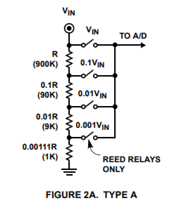
Page 2 of the previous ICL7103A/ICL8052A reference design shows two different types of resitor divider network.
Type A uses a single resistor ladder with reed relays to tap off the side of the ladder for the input to the ADC (Image copyright Renesas)
Type B uses a high-side resistor and a selection of low-side resistors in parallel (Image copyright Renesas)
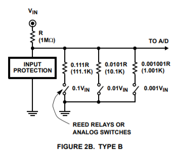
For the Type B ladder, the leakage current should be less than 10% of the current at minimum resolution to avoid distorting measurements too much. Given that I’d like to have a 1M input impedance and a 1uV resolution, that means that the current through the high side resistor is 1pA. That implies a combined leakage current in the A/D (or op-amp) and low-side switches should be less than 0.1pA. The Art of Electronics lists a few op-amps that could meet this specification, but they’re expensive.
In the Type B ladder the on-state resistance of the low-side switch is part of the divider, although at a resistance of less than 1 Ohm, this has a negligable effect on the overall divider resistance.
Finally, the impedance of the Type B ladder changes significantly depending on the voltage range, which makes it more difficult to predict the effect that the meter will have on the circuit.
By contrast, the leakage on the Type A ladder is seen directly by the load, the on-state resistance of the relays only affects the leakage current (and there will probably be a protection resisitor in that path anyway), and the only impedance variation during range changes comes as the leakage current is applied to different parts of the ladder.
I haven’t explored it completely, but the ICL7103A/ICL8052A reference design also implies that the Type A ladder can be re-used for resistance measurement, although I haven’t looked into how I would do this in my design yet.
For all of these reasons, I’m going to proceed with a Type A resistor ladder design and use reed relays to select the voltage ranges.
Following the pattern given in the ICL7103A/ICL8052A reference design, I’ve selected standard 1% resistor values for approximately 10M of input impedance. I’ve also calculated the applied voltage and power on each resistor at the maximum that I want to protect against (2kV or 0.2mA at 10M), which will help me select real resistors.
| Relative Value | Selected Value | Calculated Ratio | Voltage at 2kV input | Power at 2kV input |
|---|---|---|---|---|
| R | 9.09M | 1.00 | 1820V | 0.36W |
| 0.1 R | 909k | 0.1 | 182V | 0.036W |
| 0.01 R | 90.9k | 0.0100 | 18.2V | 3.6mW |
| 0.001 R | 9.09k | 1.00e-3 | 1.82V | 0.36mW |
| 0.0001 R | 909 | 1.00e-4 | 0.18V | 36uW |
| 0.0000111 R | 100 + 1 | 1.00e-5 | 20mV | 4uW |
By adding an additional 1-ohm resistor at the bottom of the ladder, I’m able to make the total ladder resistance add up to exactly 10.1M, which results in perfect ratios at each point in the ladder (without it, the 20mV divider is off by 1%). I put together a spreadsheet taking resistor tolerance into account, and looks like the worst-case error for a single resistor out of tolerance is equal to the tolerance, so if I use 0.1% tolerance resistors for the ladder, the extra 1-ohm resistor maintains that tolerance.
The first two resistors have significant applied voltages, and the first resistor has a significant amount of applied power, so those will probably need to be specially selected. The other resisistors have negligible applied voltage and current, so those should be easier to select.
Next post I’ll move on to selecting real resistors and start working on the schematic.
Home