Jan 08, 2018 - Nixie MultiMeter, Part 1
It’s time for me to take a quick break from the projects I’ve been working on for the past few years, and start something new.

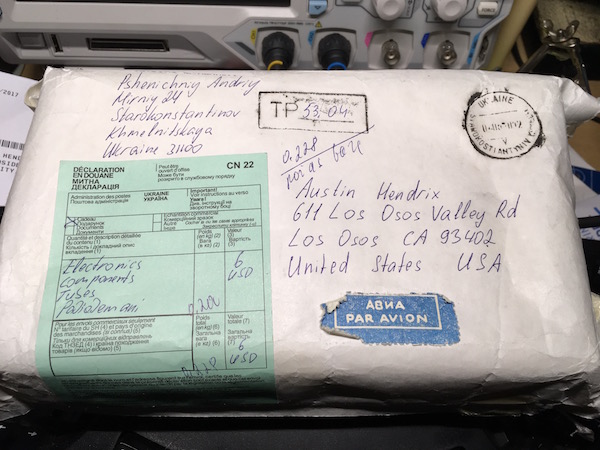
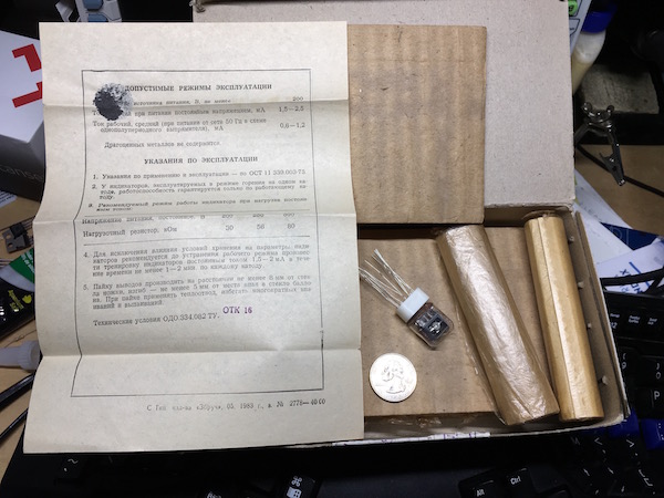
I’ve had some IN-17 Nixie tubes sitting my project box for almost 8 years now, and I think I’ve finally found a good project for them: a multimeter! I’ve always been a little disappointed with Nixie clock projects because they either keep the tubes on all the time, which shortens their lifetime, or they have some kind of circuit for turning the tubes off most of the time. I’ve also seen a lot of them, and thought it would be cool to do something different.

I do a lot of electronics work, so a desktop multimeter would be something that I could use regularly and still get a lot of life out of the Nixie tubes.
I’m going to try to post regular blog updates as a I do my design and use this blog as my design notes, instead of keeping a traditional design notebook. This means you get to see the inside of my head; hopefully it’s not too messy.
Basic Design
I’m going to start this design with the basic design of the sampling circuitry. It seems like there are a couple of approaches that I can take here:
- I can try to use the designs from my copy of The Art of Electronics and build a 6 1/2 digital multimeter similar to the Agilent 34401A.
- I can build a far simler design based on an off-the-shelf Multimeter IC, probably using a 3 1/2 or 4 1/2 digit part.
- I can try to build my own multimeter using a DAC and a Microcontroller.
- I can look for other, proven reference designs on the internet and copy those.
In addition, I suspect there will be challenges to get all of the input protection, filtering and ranging circuitry correct regardless of how accurate the meter is, and additional accuracy will likely just make all of those tasks more complicated, so I’m going to avoid the 6 1/2 digit design for now and investigate the simpler designs first.
Digits and accuracy
After a short bit of research, I can summarize digits as just that; the number of digits displayed. 1/2 digits generally indiate that the upper digit can take a limited range of values, either 0 to 1, 0 to 2 or 0 to 5, depending on the meter.
The number of digits also determines the requirements for the accuracy of the sampling circuit. For each range, the ADC circuit needs to have high enough accuracy to determine as least one bit past the least significant digit, so that the least significant digit can be estimated correctly. Mathematically, this is 0.5 / MAX
Since this is mostly focused at understanding the accuracy required from the front-end circuit and the ADC, I’m going to ignore the acutal sampling ranges for now and just focus on accuracy and ADC resolution.
Since I’m using Nixie tubes and don’t have half digits available, I’m just going to estimate the accuracy for full-digit configurations.
| Digits | Range of values | Required accuracy (%) | Resolution (bits) |
|---|---|---|---|
| 3 | 0 - 999 | 0.05% | 10 |
| 4 | 0 - 9999 | 0.005% | 14 |
| 5 | 0 - 99999 | 0.0005% | 17 |
| 6 | 0 - 999999 | 0.00005% | 20 |
The accuracy required for all of these seems a little daunting, but hopefully I can get there with careful design and component selection. I probably need to go back and read the section in The Art of Electronics about error modeling too.
The 3-digit design seems within the realm of something that I could implement on a standard microcontroller with the built-in ADC, if I can get the input voltage into the correct range.
The 4-digit design is probably out of reach for most microcontrollers, but there are plenty of standalone ADCs that would be more than adequate for the task, and probably many other standalone parts as well.
The 5-digit and 6-digit designs seem to require a lot of accuracy, but there are also a surprising number of 18-bit and 20-bit ADCs available on DigiKey for $2 or $3 each, so these might be achievable.
Existing Reference Designs
I’m going to a brief survey of the internet to see if I can find any reference designs that cover both the sampling circuitry and the range and mode selection circuitry. The examples in The Art of Electronics cover the amplifier front end and the ADC very well, but they make very little mention of the range and mode selection or input protection circuitry, and how it might affect circuit accuracy and performance.
Results:
- http://www.ti.com/lit/an/snoa592c/snoa592c.pdf ; A TI design study demonstrating how to use a TI ADD3501 to build a low-cost 3 1/2 digit multimeter with an accuracy of 0.05%. 2V, 20V, 200V and 2000V ranges, DC and AC RMS voltage modes, DC and AC RMS current modes, and Ohm modes. Looks like it uses a lot of complex selector switches to switch ranges and modes.
- https://electronics.stackexchange.com/questions/5598/auto-ranging-meter-design ; Electronics Stackexchange post describing multimeter design with a few good links about input protection: http://www.opencircuits.com/Input_protection
- https://www.eleccircuit.com/digital-multimeter-circuit-using-icl7107/ ; Seems a bit simplistic but includes a full schematic at the end. Uses the ICL7107 which seems to be designed to drive an LED display directly: https://www.intersil.com/content/dam/Intersil/documents/icl7/icl7106-07-07s.pdf
- https://www.intersil.com/content/dam/Intersil/documents/an02/an028.pdf ; Design for an auto-ranging multimeter based on an ICL7103A/ICL8052A. Discusses different types of auto-ranging circuits. I’m not quite sure how the two parts in this design are interacting, and it looks like the ICL7103A is designed to drive an LED display, but it looks like this is a design worth studying.
And that’s it for the night!
Home